Representative program design — this case study illustrates the type of engagement Shailka-Robotics is built to deliver, not a completed project.
Situation
Consider an aerospace maintenance, repair, and overhaul (MRO) operator managing a 1.2 million sq ft facility struggling with cross-functional visibility across its complex operations. The facility houses 6 aircraft maintenance bays, 3 engine overhaul shops, component repair stations, and supporting infrastructure (HVAC, compressed air, power distribution, crane systems).
Key challenges:
- Siloed facility data: Engineering models (BIM/CAD), operational schedules, equipment telemetry, and maintenance records lived in separate systems. No single environment allowed teams to reason about the facility holistically -- maintenance planners could not see spatial context, and facility engineers could not see operational load data
- Reactive maintenance patterns: Equipment failures (overhead cranes, paint booth ventilation, clean room HVAC) were addressed reactively. The maintenance team tracked work orders in a CMMS but had no spatial view of failure patterns, aging equipment clusters, or access path dependencies
- Expansion planning difficulty: The operator was evaluating a facility expansion to add two additional maintenance bays. Planning was done using 2D floor plans and static renderings, making it difficult to assess impact on utility routing, crane coverage, and material flow paths
- Regulatory documentation burden: Aviation MRO facilities require continuous compliance documentation. Inspectors needed to verify equipment placement, safety zone clearances, and environmental control system specifications -- all of which were assembled manually from disparate sources
Technical Architecture
This program design specifies a facility-scale digital twin using four integrated layers:
Geometry Composition (OpenUSD) The entire facility would be composed in a unified OpenUSD stage. BIM models (Revit exports) provide the structural envelope. Equipment geometry (cranes, ventilation units, test cells) is imported from vendor CAD files. The OpenUSD composition graph preserves the origin hierarchy of each data source, enabling non-destructive updates when equipment is moved or replaced.
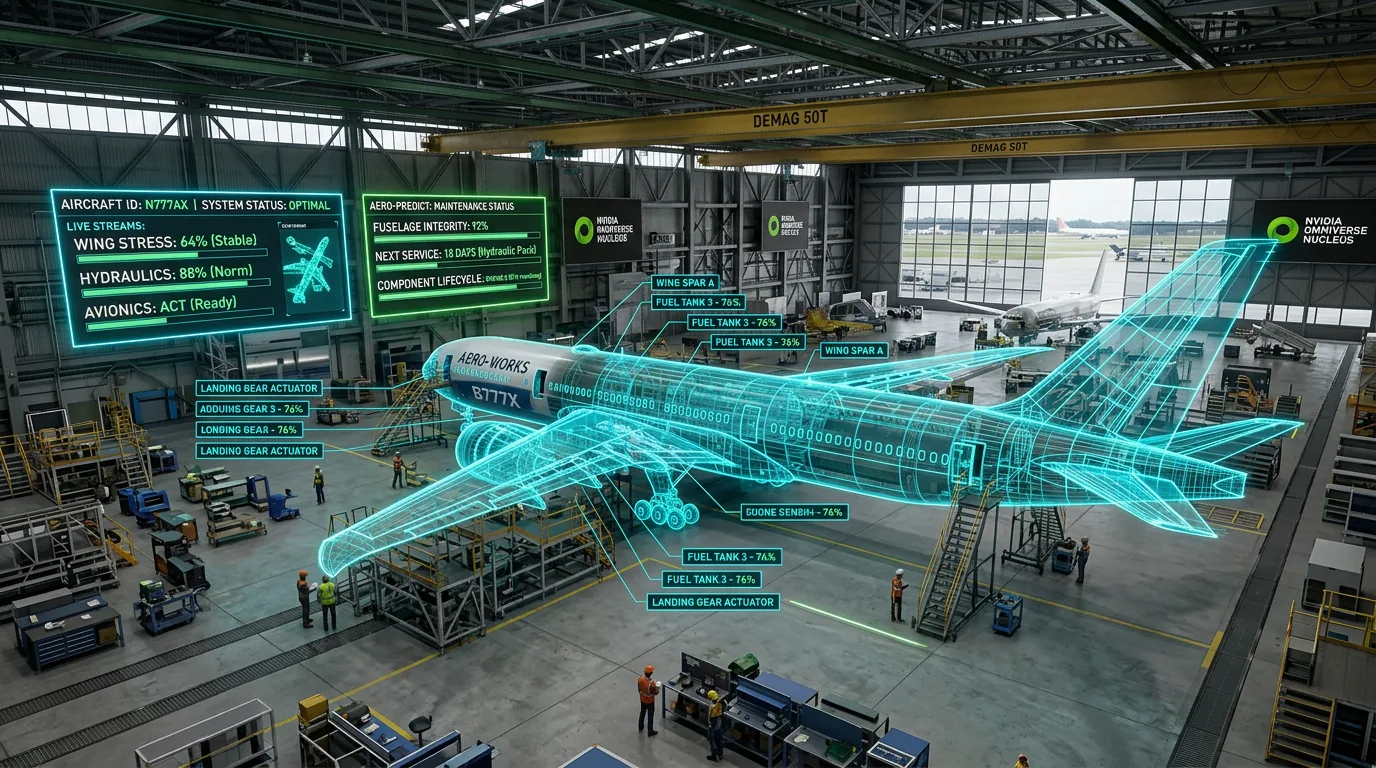
Operational Telemetry Integration IoT sensors across the facility (vibration monitors on crane motors, temperature and humidity sensors in clean rooms, power consumption meters on test cells) connect to the digital twin through a telemetry ingestion layer. Sensor data maps to the corresponding USD prim for each piece of equipment, enabling spatial queries like "show me all equipment with vibration readings above threshold in Bay 3."
Predictive Maintenance Overlay Historical maintenance records, equipment age data, and telemetry trends combine in a predictive maintenance model. The model identifies equipment approaching failure probability thresholds and surfaces them as spatial annotations in the digital twin -- maintenance planners can visualize upcoming work spatially rather than as a flat work order list.
Collaboration and Review (Omniverse + Nucleus) Nucleus provides real-time synchronization so that engineering, maintenance, operations, and expansion planning teams work in the same environment simultaneously. Role-based views filter the information density: maintenance teams see equipment health overlays, facility engineers see structural and utility routing, and expansion planners see impact zone visualizations for proposed changes.
Implementation Timeline
| Phase | Duration | Deliverable | |---|---|---| | BIM/CAD import and USD composition | 5 weeks | Unified facility stage (1.2M sq ft) | | Telemetry integration and sensor mapping | 4 weeks | Live IoT data on 340+ equipment prims | | Predictive maintenance model deployment | 4 weeks | Spatial failure probability overlays | | Collaboration platform and role-based views | 3 weeks | Multi-team concurrent review environment |
Projected Impact
- 25% maintenance cost reduction targeted in the first year through predictive scheduling and spatial conflict resolution
- 340+ equipment assets mapped with live telemetry in the digital twin
- Expansion planning cycle reduced from 12 weeks to 4 weeks by evaluating utility routing, crane coverage, and material flow impacts in the twin before physical design
- 60% reduction in regulatory inspection preparation time projected -- compliance documentation generated directly from the digital twin's spatial and equipment data
- Early detection of utility routing conflicts during expansion planning that would otherwise require costly rework during construction
Expected Outcome
An aerospace MRO operator following this program would establish a living digital twin that serves as the facility's spatial operating system. Maintenance planning shifts from reactive work order management to predictive, spatially-aware scheduling. Expansion planning teams validate additional bay configurations entirely in the digital twin before committing to construction documents. The program model is designed for rollout across multiple MRO facilities.